Workload
Separate document search, video inference and training; check concurrent users, data volumes, GPU and memory demand, and operating hours.
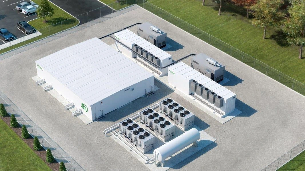
AI Infrastructure, Designed from the Workload Out.
Starting with Physical AI data from cameras, Edge AI, drones, robots and industrial equipment, Standard Link designs communications, power, cooling, GPUs and distributed AI data centers together.
Combined with GEC's modular power, cooling and EPC technology, this is a vision for infrastructure balancing closed-network operation, scalability and high-density AI processing.
SOURCE IMAGE / GEC PROFILE P.29 / MODULAR DATA CENTER CONCEPT
The 20-foot, 5-rack, 27kW configuration on our public site is a reference starting point. The definition of 27kW, GPU selection, cooling, installation and maintenance are confirmed for each project.
Separate document search, video inference and training; check concurrent users, data volumes, GPU and memory demand, and operating hours.
Check site power availability, redundancy, UPS and the scope and definition of power ratings.
Check expected heat, cooling method, outdoor conditions, noise and maintenance access together with the GPU configuration.
PoC, small-scale introduction and staged expansion as usage grows.
If Edge AI or local processing alone meets the objective, the assessment may recommend not introducing an AIDC.
Discuss a small-AIDC preliminary assessmentThese are reference configurations for design and construction discussions, not facilities owned or operated by SLL. The parties responsible for design, supply, installation and operations are confirmed per project.
Training, adaptation of existing models, evaluation, multi-video inference and data management are different workloads. We also assess whether existing servers or cloud services are sufficient; this small configuration is not presented as capable of every training task.
Rather than starting with power, racks, cooling and connections, Standard Link works backwards from the Physical AI workload: what AI vision and Edge AI capture, where decisions are made and what is learned.
Design around real workloads from cameras, sensors, drones and industrial equipment.
Design Device Edge, Regional AI Nodes and core AI data centers as one operating system.
Use IP to support seeing, detecting, integrating, deciding, recording and learning.
Integrate GEC power, cooling and modular EPC with Japanese applications, regulations and partner arrangements.
Match closed-network design, placement, power, cooling and expansion units to confidentiality, regional needs, investment returns and actual demand.
Manufacturing / research / healthcare / finance / critical infrastructure / AI developers
Local government / industrial parks / ports and airports / universities / regional power / agricultural regions
International investors / developers / infrastructure funds / general contractors / energy companies
Instead of continuously sending all raw data to a central location, select data at the edge and share necessary information in stages according to the application and contract.
HOLONIC Eyes, cameras, sensors, drones, robots, factory and agricultural equipment, and HOLONIC Edge AI.
An intermediate layer that integrates multiple sites locally for shared use with lower bandwidth demand and latency.
A closed-network, sovereign core handles long-term storage, integrated analysis, training, distribution and audit.
Power, cooling and data-hall modules are manufactured and integration-tested in a factory, then delivered while on-site construction proceeds in parallel. Capacity is added as AI demand grows to limit initial investment.
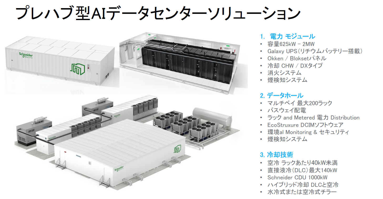
Image text translation
Reference translation prepared for this website. The source image is unchanged; this is not an original or certified translation.
Prefabricated AI data center solution
1. Power module
2. Data hall
3. Cooling technology
The three illustrations show a power module, an internal rack row and an overall facility layout. The numbered list on the right groups power, data-hall and cooling functions. Schneider Electric branding remains part of the supplier image.
Site note: these are supplier reference configurations, not a guarantee for every project. Capacity definitions, applicable equipment and site conditions require confirmation.
Figures describe GEC reference configurations. Actual capacity, rack count, cooling and PUE depend on equipment, climate, redundancy, site and power conditions.
Configure power reception, transformation, UPS and storage for the project.
Integrate racks, distribution, monitoring and security.
Select air or direct liquid cooling for density and location.
Image supplied from PDF page 18. The specification summary on the right is adapted for the web; capacity and methods vary by project.
This is a target for projects with site, power, permits, procurement and other prerequisites in place, where factory prefabrication and on-site construction run in parallel. Completion and start-up dates are not guaranteed.
Staged-expansion concept using N+1 power and cooling blocks. Piping and equipment details are designed individually.
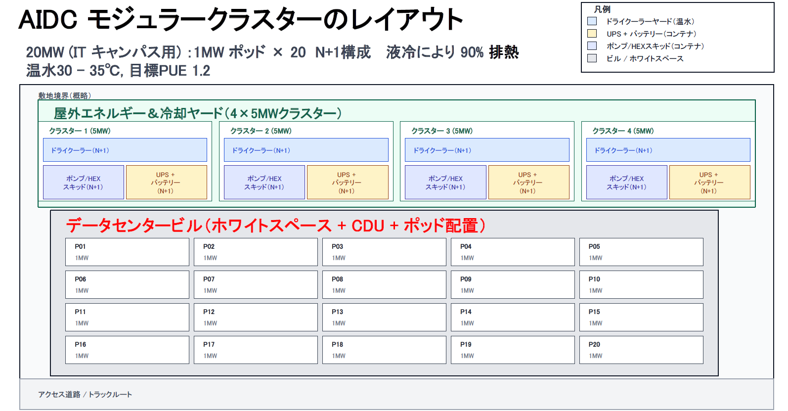
Image text translation
Reference translation prepared for this website. The source image is unchanged; this is not an original or certified translation.
AIDC modular cluster layout
20 MW for an IT campus: twenty 1 MW pods, with an N+1 configuration. The source layout specifies 90% heat removal through liquid cooling, warm water at 30–35°C, and a target PUE of 1.2.
Legend
Approximate site boundary / outdoor energy and cooling yard: four 5 MW clusters
Clusters 1, 2, 3 and 4 are each labeled 5 MW.
Data center building: white space, CDU and pod layout
Pods P01–P20 are each labeled 1 MW, arranged in four rows of five: P01–P05, P06–P10, P11–P15 and P16–P20.
Within the approximate site boundary, the four outdoor clusters occupy the upper zone; the building with twenty pods is below. The access road / truck route runs along the bottom.
Site note: this is a reference layout. The heat-removal ratio and PUE are design figures or targets, not verified operating results or project-wide guarantees.
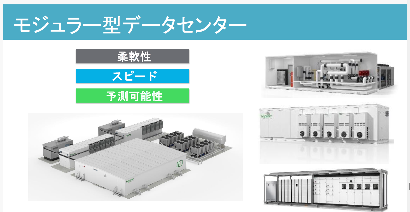
Image text translation
Reference translation prepared for this website. The source image is unchanged; this is not an original or certified translation.
Modular data center
The left side lists the three intended benefits and shows the overall facility. The right side illustrates cooling, power and rack modules. Schneider Electric marks remain in the supplier image.
Start with the capacity needed and add as demand grows.
Run factory manufacturing and site works in parallel to aim for earlier operation.
Manage quality and schedule through integration-tested modules.
Key points from PDF page 30 adapted into three web cards.
Standard Link's AI data center approach is not limited to building a large facility all at once.
From all-in-one AI nodes in the tens-of-kW range at factories, universities, hospitals, local government and research sites, to dedicated enterprise or regional data centers of 625kW to 2MW and 20MW-class AI campuses, expansion is staged around purpose, power conditions and AI demand.
Small container-based edge AI data centers can serve as an entry point for enterprise and local-government AI infrastructure.
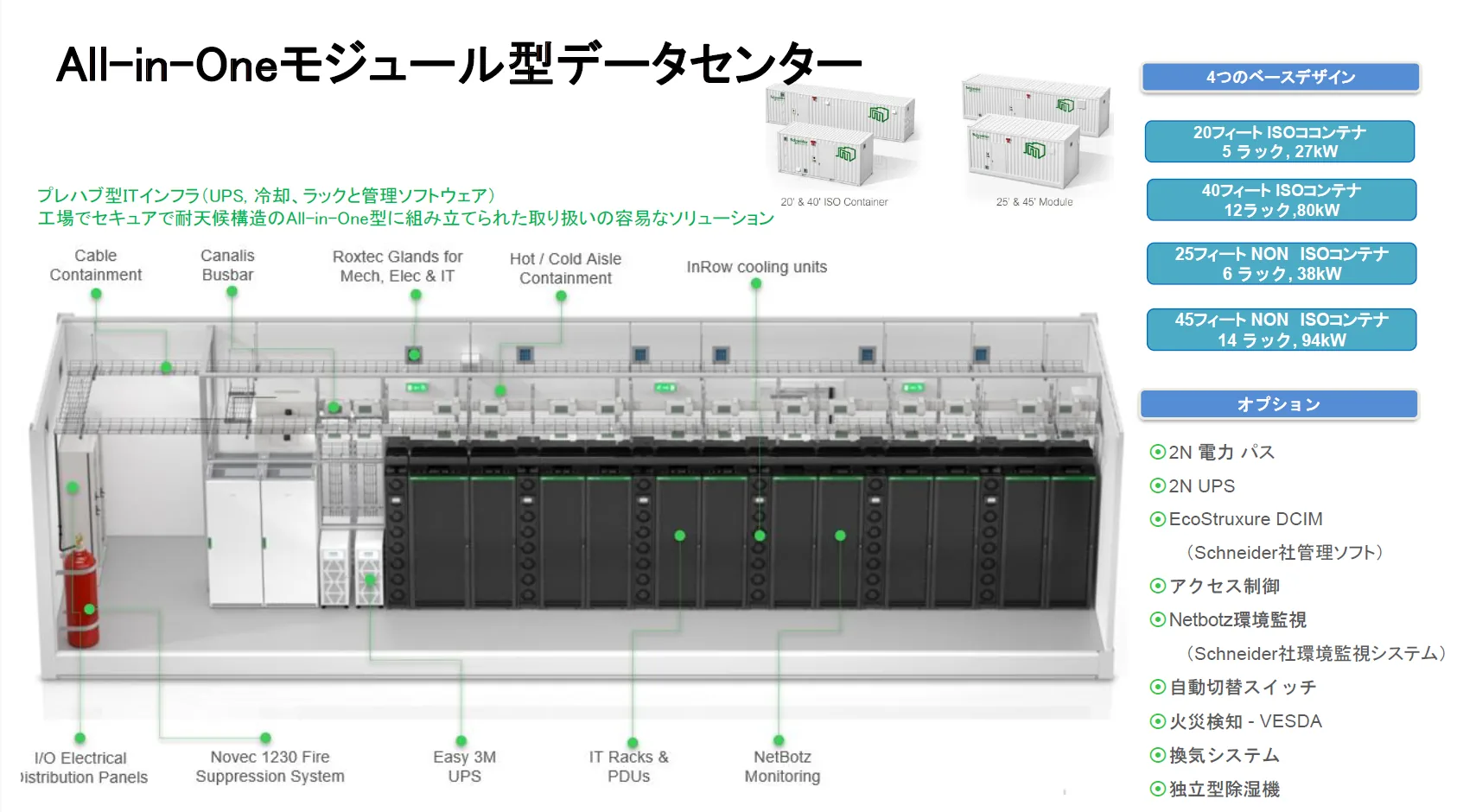 GEC REFERENCE / INTERNAL CUTAWAY
Image text translation
Reference translation prepared for this website. The source image is unchanged; this is not an original or certified translation.
All-in-One Modular Data Center
Prefabricated IT infrastructure: UPS, cooling, racks and management software.
A manageable all-in-one solution assembled at the factory in a secure, weather-resistant structure.
Four base configurations
Equipment labels in the cutaway
Options
How to read the diagram: leader lines connect the equipment labels to their locations inside the central container cutaway. The four base configurations and optional equipment are listed separately on the right.
Site note, not part of the source image: the power figures are configuration labels. Their definition, GPU configuration, cooling method, installation, delivery and maintenance conditions require project-specific confirmation; no IT-load, input-power or contracted-power definition is inferred here.
Reference small AI node for low-latency inference and confidential-data management near the field.
Dedicated enterprise and research AI infrastructure for constrained sites, supporting progression from PoC to production.
Standardized modular data center reference configuration for full-scale enterprise and research AI operations.
Regional distributed AI node reference configuration connecting multiple facilities, companies and local-government systems.
From a five-rack field AI site to a 20MW-class AI campus, the same modular approach scales with AI demand.
Reference designs of 5 to 14 racks for inference, closed-network AI, business continuity and low-latency processing at factories, universities, hospitals and local-government sites.
GPU data centers up to 2MW, considering dedicated enterprise GPUs, regional AI, high-density racks, liquid cooling, BESS and multiple modules.
Large-scale training, shared use, high-density GPUs, additional 1MW pods and multi-cluster regional AI infrastructure.
Begin with the required use case: PoC, on-site inference or enterprise private AI.
Locate it where data originates: factories, hospitals, universities, ports and local-government sites.
Add modular capacity as rack, power, cooling and GPU requirements increase.
Connect AI nodes to closed networks, Regional AI Nodes and HOLONIC DATA CENTER.
AI computing resources can operate continuously only when stable power reaches high-density racks and generated heat is removed as designed.
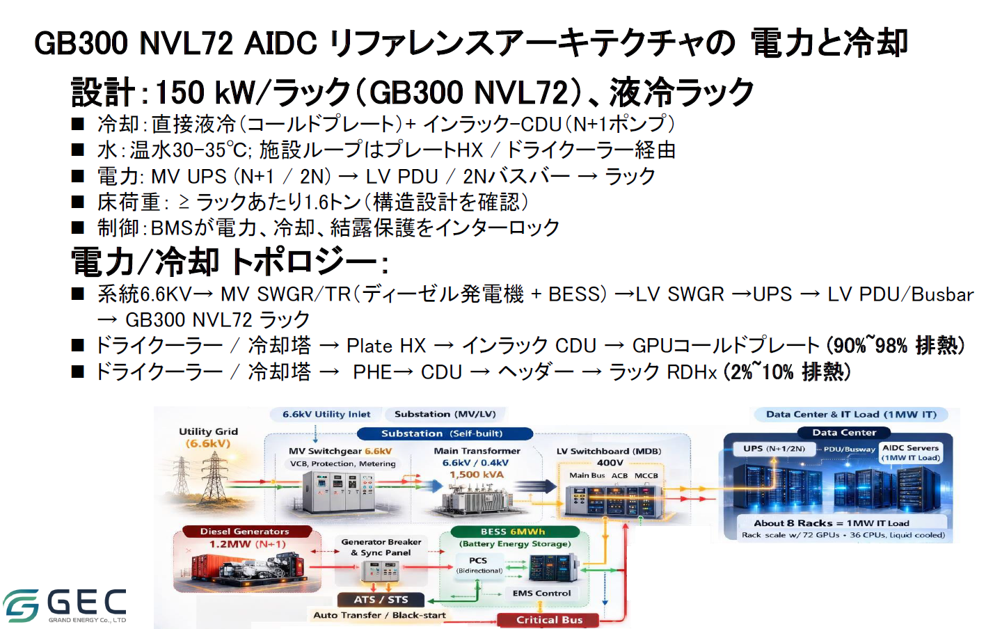
Image text translation
Reference translation prepared for this website. The source image is unchanged; this is not an original or certified translation.
Power and cooling for the GB300 NVL72 AIDC reference architecture
Design: 150 kW per rack (GB300 NVL72), liquid-cooled racks
Power / cooling topology
6.6 kV utility supply → MV switchgear / transformer (diesel generator + BESS) → LV switchgear → UPS → LV PDU / busbar → GB300 NVL72 rack.
Dry cooler / cooling tower → plate HX → in-rack CDU → GPU cold plate (90%–98% heat removal).
Dry cooler / cooling tower → PHE → CDU → header → rack RDHx (2%–10% heat removal).
Labels in the lower power-system diagram
The main power path runs left to right from the utility to the data center. Diesel generators and BESS are connected below through switching, synchronization and the critical bus. GEC / GRAND ENERGY Co., LTD identifies the source.
Site note: source design figures and approximations are reproduced without recalculation. In particular, 150 kW per rack and approximately eight racks per 1 MW are separate source labels, not a newly reconciled calculation. Electrical, structural, thermal and equipment suitability requires project-specific engineering confirmation.
A simplified web summary of GEC reference designs including 150kW-class racks. It does not guarantee support for individual GPU models.
| Rack density | Cooling option | Design considerations |
|---|---|---|
| Up to around 40kW | Air cooling | Room airflow and fan walls |
| Around 40-50kW | Close-coupled cooling | InRow, rear-door and similar options |
| Above 50kW | Consider liquid cooling | CDU and facility water loops |
| Above 100kW | Direct-to-chip and related methods | High-density heat recovery and redundancy |
Indicative only. Actual design depends on IT equipment, climate, redundancy, water-use policy and operating conditions.
Design not only data collection, but who may use it, for what purpose and to what extent. Closed-network configuration, storage, learning, distribution and audit form one governance framework.
We envisage regional AI nodes with local government, universities, businesses and power providers, balancing everyday industrial use with continuity during disasters.
River, road and slope monitoring, drone search, disaster-video analysis and regional AI operation during communications loss.
Use field data from agriculture, livestock, factories, logistics, ports, tourism and transport within the region.
Assess renewable energy, BESS, demand response, grid capacity, waste-heat use and reduced water consumption per project.
Include noise, heat, water, landscape, fuel, resident engagement, local employment and education in project design.
Instead of fixing capacity first, design power availability, anchor workloads, start-up timing and expansion units within one investment plan.
Integrate power capacity, connection timing, BESS and renewables.
Expand with demand in units such as 625kW to 2MW.
Plan for high-density racks, liquid cooling and future GPUs.
Aim for earlier operation through factory prefabrication and parallel construction.
Plan demand from Physical AI applications and customer workloads.
Standard Link contributes Physical AI design and Japanese-market integration; GEC contributes power, cooling and modular EPC. These distinct specialties come together in one project design.
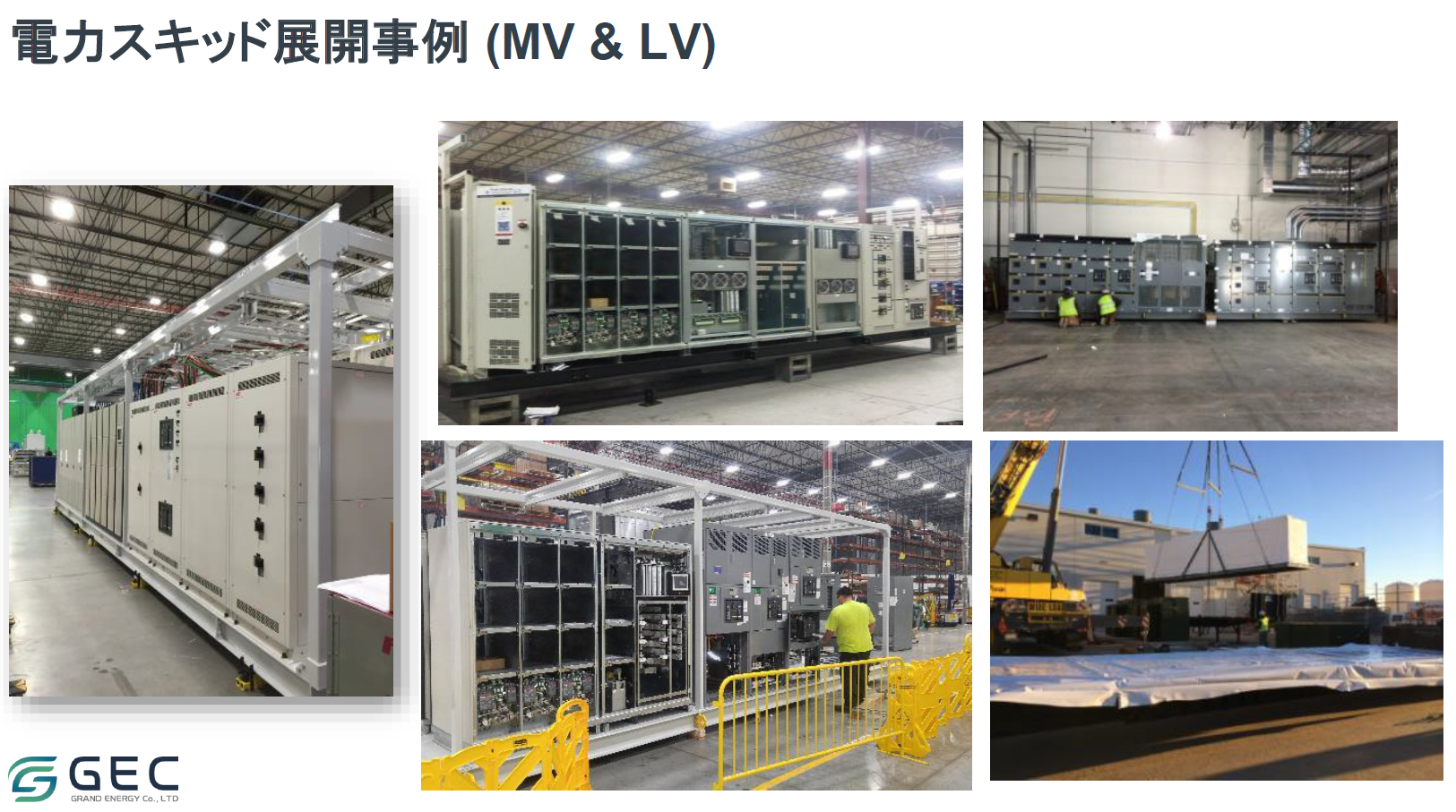
Image text translation
Reference translation prepared for this website. The source image is unchanged; this is not an original or certified translation.
Power-skid deployment examples (MV and LV)
Five supplier photographs show switchgear / power-skid assemblies inside a factory, assembly work and a crane lifting a module into place. MV means medium voltage; LV means low voltage.
Source mark: GEC / GRAND ENERGY Co., LTD
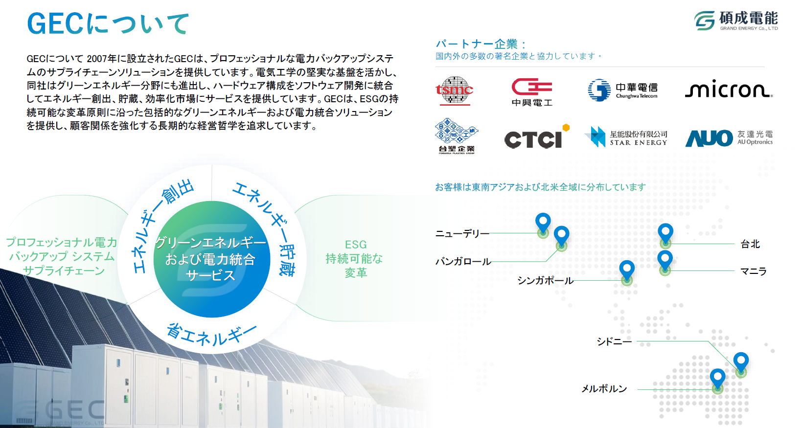
Image text translation
Reference translation prepared for this website. The source image is unchanged; this is not an original or certified translation.
About GEC / 碩成電能 / GRAND ENERGY Co., LTD
Founded in 2007, GEC provides supply-chain solutions for professional power-backup systems.
Building on its electrical-engineering foundation, the company has expanded into green energy, combining hardware configurations with software development to serve energy generation, storage and efficiency markets.
GEC provides comprehensive green-energy and power-integration solutions aligned with ESG principles for sustainable transformation, pursuing a long-term management philosophy that strengthens customer relationships.
Partner companies: the source states that GEC works with numerous established companies domestically and internationally.
Green-energy and power-integration services
The source text states that customers are distributed across Southeast Asia and the Northern Hemisphere.
The lower-left ring connects generation, storage and efficiency around integrated services. Partner logos appear above the location map on the right.
Site note: these are GEC's source statements, not claims that Standard Link has partnerships with each named company. The source's Northern Hemisphere wording and its Australian map locations are retained as separate source information, not silently corrected.
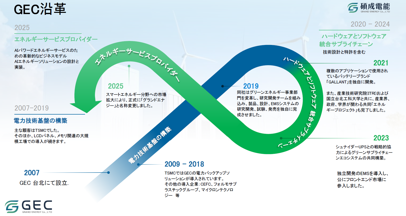
Image text translation
Reference translation prepared for this website. The source image is unchanged; this is not an original or certified translation.
GEC history / 碩成電能 / GRAND ENERGY Co., LTD
2007–2019: building a power-technology foundation
The source identifies TSMC as the main customer, followed by deployments at large LCD-panel and memory-related factories.
2020–2024: integrated hardware and software supply chain, including technical design and patents
The source also reports completion of a joint energy project involving industry, government and academia together with the Industrial Technology Research Institute (ITRI) and the university named in the source as National Taipei University of Technology.
The source states that an independently developed EMS was introduced and that the company publicly entered the front-end market.
2025: energy service provider
An innovative business model for AI-powered energy services; design and implementation of AI energy solutions.
An infinity-shaped band links the power-technology foundation, hardware/software integration and energy services, with the dated milestones positioned around it.
Site note: this is the supplier's historical account, not Standard Link's corporate history, partnerships or university-participation record. Names and dates are presented as source material, not new endorsements.
Third-party company names and trademarks on page 3 are part of GEC-supplied materials. All trademarks belong to their respective owners.
GEC's history and business development are summarized to clarify its role alongside Standard Link.
Established in Taipei, building technology foundations in backup power and supply networks.
Developed power-infrastructure implementation capabilities through large manufacturing-site deployments.
Expanded into green energy, integrating R&D and EMS.
Brought hardware, software, design and IP into one supply framework.
As Grand Energy, expanded into AI-enabled energy design and implementation.
These are partner achievements based on GEC and Standard Link public materials, not construction completed solely by Standard Link.
Read the strategic partnership announcementTrack record, development, reference configurations and concepts are distinguished. Targets are not guarantees, and proposed facilities are not described as under construction or operating.
| Item | Current status | Notes |
|---|---|---|
| Strategic partnership with GEC | PARTNERSHIP ESTABLISHED | Strategic business partnership announced in April 2026 |
| Japanese-market development | IN PROGRESS | Developing projects and collaboration partners |
| AI workload design | IN DEVELOPMENT | Requirements derived from Physical AI applications |
| Modular AIDC configurations | REFERENCE ARCHITECTURE | GEC reference configurations redesigned for each project |
| First project | TARGET: FY2026 | Target for starting work; not under construction or operating |
| Regional distributed nodes | PLATFORM VISION | Concepts with local government, universities and regional businesses |
| Data Flywheel | PLATFORM DEVELOPMENT | Developing infrastructure for training, distribution and audit |
Eight months is a conditional target, PUE is a design target and specifications describe reference configurations. They are not project-specific guarantees.
Sovereign AI means using AI while retaining data, models and IP domestically. We combine modular data-center capabilities through our strategic partnership with Taiwan-based GEC and vertically integrated technology from the edge to data infrastructure to advance sovereign AI from concept to implementation.
We seek deployment partners pursuing generative AI and AI agents in closed environments in manufacturing, finance, healthcare and local government; construction and deployment partners for land, power and construction; and sales partners for joint customer proposals.
Our policy is to become the first user ourselves by migrating our own AI development and operations to the same infrastructure.
Companies and local government seeking generative AI and AI agents in closed environments
Companies responsible for land, power and construction
Companies working with us on customer proposals
Applications, scale, schedule, closed-network requirements, shared use and investment conditions are reviewed individually.
We design actual AI workloads, edge processing, closed networks, learning and model distribution together. Rather than assuming a capacity, we work backwards from what is processed and where.
We first assess workloads and existing facilities, then size the configuration around GPU and memory, power and cooling, communications and maintenance. The 20-foot, 5-rack, 27kW design is a published reference configuration; the definition of 27kW is confirmed per project. Start small and consider expansion with usage.
No. It is an operational-start target for projects with land, power, permits, procurement and construction conditions in place, where factory prefabrication and site construction run in parallel.
It can be designed around requirements. We check data categories, users, connected sites, retention periods, training use and audit needs before defining the configuration.
We support joint planning for regional AI infrastructure, considering industry, research, disaster response, energy and continuity during emergencies together.
Discussions follow review of land, power, anchor workloads, SPV, EPC, operations and expansion plans.